
Meaning and mechanism
When the coil current changes, the magnetic flux through the coil also changes. Consequently, the induced electromotive force generated as a result is in the direction of reducing the current change.
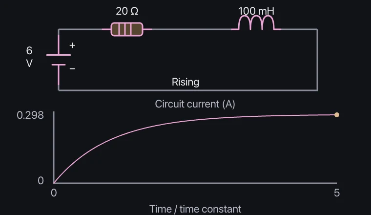
Immediately after turning the power on, the coil strongly resists the increase in current. As time passes and the change in current slows down, the resistance approaches the final current V/R.
Relationships and conditions
The time constant of a DCRL circuit is τ=L/R, and the increasing current is (V/R)(1−e⁻ᵗ/τ). Approximately 63.2% is the final value after τ.
Real coils exhibit parasitic resistance and parasitic capacitance. The sudden interruption of the current path results in a transient voltage that is treated separately from the simple on-off curve.
What to observe in the simulation
τ = L/R; after one time constant the rising current reaches about 63.2% of its final value.
Coil resistance, parasitic capacitance and switch arcing are omitted. Experiment on screen; do not reproduce this with real power supplies, outlets or high voltage.
Key relationships and symbols
τ = L/R · I = (V/R)(1−e^(−t/τ))
| Symbol | Meaning | Unit |
|---|---|---|
| L | Inductance | H |
| R | Total series resistance | Ω |
| τ | Time constant L/R | s |
Worked example
During current rise in a 6 V, 20 Ω circuit, what is the current at t=τ?
About 0.190 A
Common misconceptions
- Self-induction is not an effect that always eliminates the current itself, but rather a reaction to changes in the current.