
Meaning and mechanism
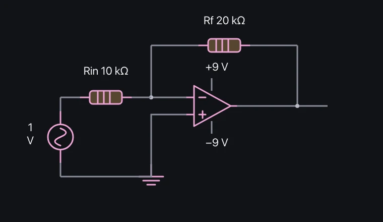
An amplifier with a large open-loop gain can be designed to reduce input differences by returning a portion of the output. The direction of the connection between the input and output is important.
In an ideal negative feedback circuit performing linear operation, it is assumed that the two input potentials are nearly equal. The virtual grounding in an inverting circuit differs from the actual grounding with a physical wire.
Relationships and conditions
The inverting gain is −Rf/Rin, and the non-inverting gain is 1+Rf/Rin. If the calculated output exceeds the supply range, the circuit cannot maintain the linear gain given by these equations.
The approximation requires small input currents and sufficient gain and bandwidth. Do not apply the virtual-short approximation unchanged to a saturated amplifier or a positive-feedback circuit.
What to observe in the simulation
Inverting gain is −Rf/Rin and non-inverting gain is 1+Rf/Rin; output stays within the rails.
Input current, offset, slew rate and bandwidth are omitted. Only supply saturation is included. Experiment on screen; do not reproduce this with real power supplies, outlets or high voltage.
Key relationships and symbols
Ainv = −Rf/Rin · Anoninv = 1+Rf/Rin · Vout = clamp(AVin,−Vs,Vs)
| Symbol | Meaning | Unit |
|---|---|---|
| Rf | Feedback resistance | Ω |
| Rin | Input resistance | Ω |
| Vs | Supply voltage magnitude | V |
Worked example
For a non-inverting circuit with the same resistors, what is the output at +4 V input with ±9 V supply rails?
9 V
Common misconceptions
- The two input voltages of a differential amplifier are not always the same for all circuits and states.