
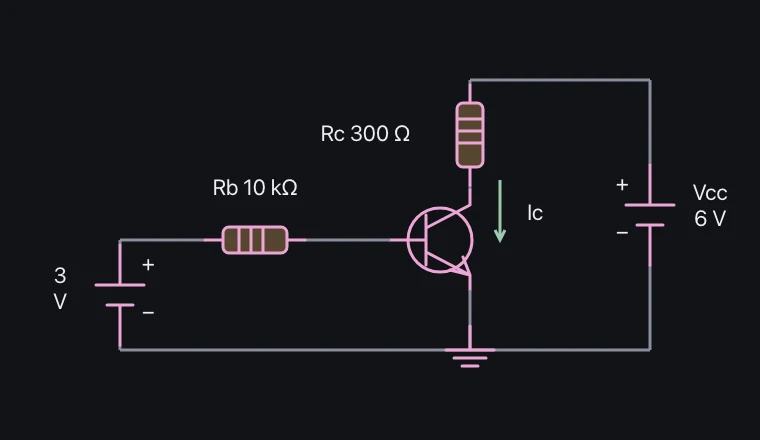
Meaning and mechanism
If the base current is very low, it is possible to use a circuit where the load current is cut off. When the operation is increased, the collector current becomes larger, approaching the limit set by the external circuit.
In the active region, Ic≈βIb, but when entering saturation, the load resistance and power supply limit the current. Even if you increase the base current, the output does not increase at the same ratio.
Relationships and conditions
The experiment compares Ib=max(0,(Vin−0.7)/Rb) with the limit of the applied current. Each value represents a simplified approximation of a specific component, and is not the exact boundary value for all transistors.
The actual β value varies depending on the current and the component, and switching also involves storage time and parasitic capacitance. We differentiate between an ideal logic switch and its actual operating range.
What to observe in the simulation
Ic = βIb applies only in the active region; the load limits current in saturation.
Temperature, leakage, dynamic transistor effects and actual LED voltage drops are omitted. Experiment on screen; do not reproduce this with real power supplies, outlets or high voltage.
Key relationships and symbols
Ib = max(0,(Vin−0.7)/Rb) · Ic = min(βIb,(Vcc−0.2)/Rc)
| Symbol | Meaning | Unit |
|---|---|---|
| Ib, Ic | Base and collector currents | A |
| β | Approximate current gain in the active region | Dimensionless |
| Rb | Base series resistance | Ω |
Worked example
What is the collector-emitter voltage when the same circuit saturates?
0.2 V
Common misconceptions
- If Ic=βIb is applied without restriction until a saturated state, it leads to an inaccurate prediction of the load current.