
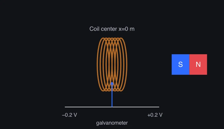
The difference between magnetic field and magnetic flux
The magnetic field B is a vector defined at every point in space, and the magnetic flux Φ represents the amount of magnetic field passing through a given surface. In a uniform field and a plane, Φ = BAcosθ, and θ is the angle between the magnetic field and the direction perpendicular to the surface.
Moving a magnet changes the magnetic field around the coil and therefore its magnetic flux. Flux can also change if the coil’s area or orientation changes, even with a stationary magnet. Conversely, if flux is constant, a stationary coil has no EMF induced by this mechanism, even in a strong magnetic field.
Faraday's law examines the rate of change of magnetic flux.
For an N-turn coil with the same flux through each turn, induced EMF is ε = −N dΦ/dt. The same flux change produces a larger EMF if it occurs in less time. More turns also give a larger EMF for the same rate of flux change.
Electromotive force is the value expressed in volt units representing the energy supplied per unit of charge. While electromotive force can arise even when a circuit is open, a continuous current flow requires a closed path. In a simple circuit consisting only of a resistor, the current is calculated as I = ε/R.
What does the negative sign in the Lorentz law signify?
The magnetic field created by an induced current is not the original magnetic field itself, but rather the direction in which it opposes the change in that original magnetic field. When a magnetic field increases as it passes through a coil, the induced current attempts to reduce that increase. Conversely, when a magnetic field decreases as it passes through a coil, the induced current attempts to reduce that decrease. Changing the direction or polarity of a magnet can also cause the direction of the induced current to change.
Lenz's law is connected to the principle of energy conservation. When a current is generated in a generator, external work is required to move a magnet or a coil. The experiment is an approximation, using a defined magnetic field distribution and circuit resistance, and does not fully reproduce the self-induction of the coil and all actual losses.
Key relationships and symbols
Φ = BAcosθ (uniform magnetic field) · ε = −N dΦ/dt · I = ε/R (resistive circuit)
| Symbol | Meaning | Unit |
|---|---|---|
| Φ | Magnetic flux through one turn | Wb |
| B | Magnetic field magnitude | T |
| ε | Induced EMF | V |
| N | Number of coil turns | trial |
Worked example
If one side of a coil, measured 100 times, exhibits a flux increase of 0.2 seconds, and the flux increases by 0.001 Wb, what is the result?
The average induced EMF has magnitude 100 × 0.001 / 0.2 = 0.5 V. In a closed resistive circuit with total resistance 10 Ω, the average current has magnitude 0.05 A. The sign depends on the chosen surface-normal direction and current direction.
Common misconceptions
- If the magnet is stationary and the coil remains unchanged, the magnetic field is strong, the current will not continuously flow simply because of the strength of the magnetic field.
- Lenz's law does not necessarily oppose the magnetic field; rather, it determines the direction in which the magnetic field changes.