
Meaning and mechanism
Unlike combination logic, where the output is determined solely by the current input, sequential logic maintains a stored state. Consequently, even with the same input, the result can vary depending on the past state.
The “ascent edge D flip-flop” stores the ‘D’ at the point where the clock transitions from 0 to 1. This is an idealized model that maintains the output state even when the ‘D’ changes between edges.
Relationships and conditions
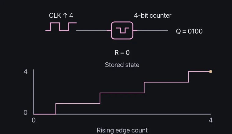
At the clock edge, Qnext=D. A 4-bit binary counter represents 0 through 15, so it returns to its initial state after 16 increments.
In actual circuits, there are setting and maintenance times, and radio delays. Neither the forbidden state nor meta-stability can be fully explained using a model with no delay, 0·1.
What to observe in the simulation
A D flip-flop stores input only on rising edges; a 4-bit counter repeats every 16 clocks.
Metastability and propagation delay are omitted. The forbidden SR state is not treated as a valid bit. Experiment on screen; do not reproduce this with real power supplies, outlets or high voltage.
Key relationships and symbols
D-FF: Qnext = D (↑CLK) · counter = (Q₀+n) mod 16
| Symbol | Meaning | Unit |
|---|---|---|
| D, Q | Data input and stored output | 0 or 1 |
| ↑CLK | Rising clock edge | Event |
Worked example
For a D flip-flop with Q=1 and D=0, what is Q when the clock falls from 1 to 0?
1
Common misconceptions
- The output of the rising edge flip-flop does not continuously follow the input as long as the clock is 1.